10+ bgp network diagram
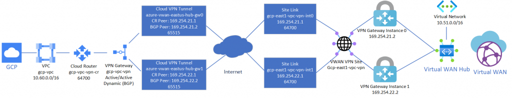
BGP container functionalities are broken down as follows. The following diagram shows a simple example of this highly available setup.

Primary On Mpls Network Backup On Internet Ll Ip Mpls Com
If your virtual network used the address space 1000016 you can advertise 100008.

. The 1 is the group number for HSRP. The following diagram shows the IPsec VPN tunnels established between on-premises VPN device 1 and the Azure VPN gateway instance pair. Runs one of the supported routing-stacks.
AWS Direct Connect components. Telnet was developed in 1969. R101show run begin bgp router bgp 1 network 17216100 mask 2552552550.
It programs custom dynamic routes based on the BGP advertisements that it receives from a peer. The following diagram shows a high-level overview of how AWS Direct Connect interfaces with your network. The neighbor 2222 update-source Loopback0 type of command specifies that the connection will be established with the Loopback interface address.
When looking at the BGP Update message from R111 1132 towards R11 1131 we can see multiple BGP attributes along with their value. Optional You can configure Bidirectional Forwarding Detection BFD on your network. Lifecycle of subnet routes.
Tier-0 SR does routing lookup and sends the packet to the physical router following the BGP route which routes it to 19216810010. Router 6 R6 is a part of AS 600 which has eBGP peering with ISP-A and ISP-B. Check to see if the route is in the BGP routing table.
For example if a subnet or peering subnet route exists for the 10701024 destination and one or more Cloud Routers in the VPC network receive the 10701025 prefix via BGP Google Cloud uses the subnet or peering subnet route and ignores the conflicting custom dynamic route. But you cant advertise 1000016 or 1000024. Router bgp 65010 bgp router-id interface Loopback0 bgp log-neighbor-changes network 10000 mask 2552552550 network 101100 mask 255.
1921681254 will be the virtual gateway IP address. Peering is settlement-free also known as bill-and-keep or sender keeps all meaning that neither party pays the other in association with the exchange of traffic. Cloud Router is a fully distributed and managed Google Cloud service that uses the Border Gateway Protocol BGP to advertise IP address ranges.
This document uses the network setup shown here. Consider this simple network where R111 advertises the 101010024 route to the AS 11 BGP peer. In computer networking peering is a voluntary interconnection of administratively separate Internet networks for the purpose of exchanging traffic between the down-stream users of each network.
1 2552552550 negotiation auto no mop enabled no mop sysid. Even though the container is named after the routing-protocol being used bgp in reality these routing-stacks can run various other protocols such as ospf isis ldp etc. SW1 SW2 configinterface Vlan 1 config-ifstandby 1 ip 1921681254 Use the standby command to configure HSRP.
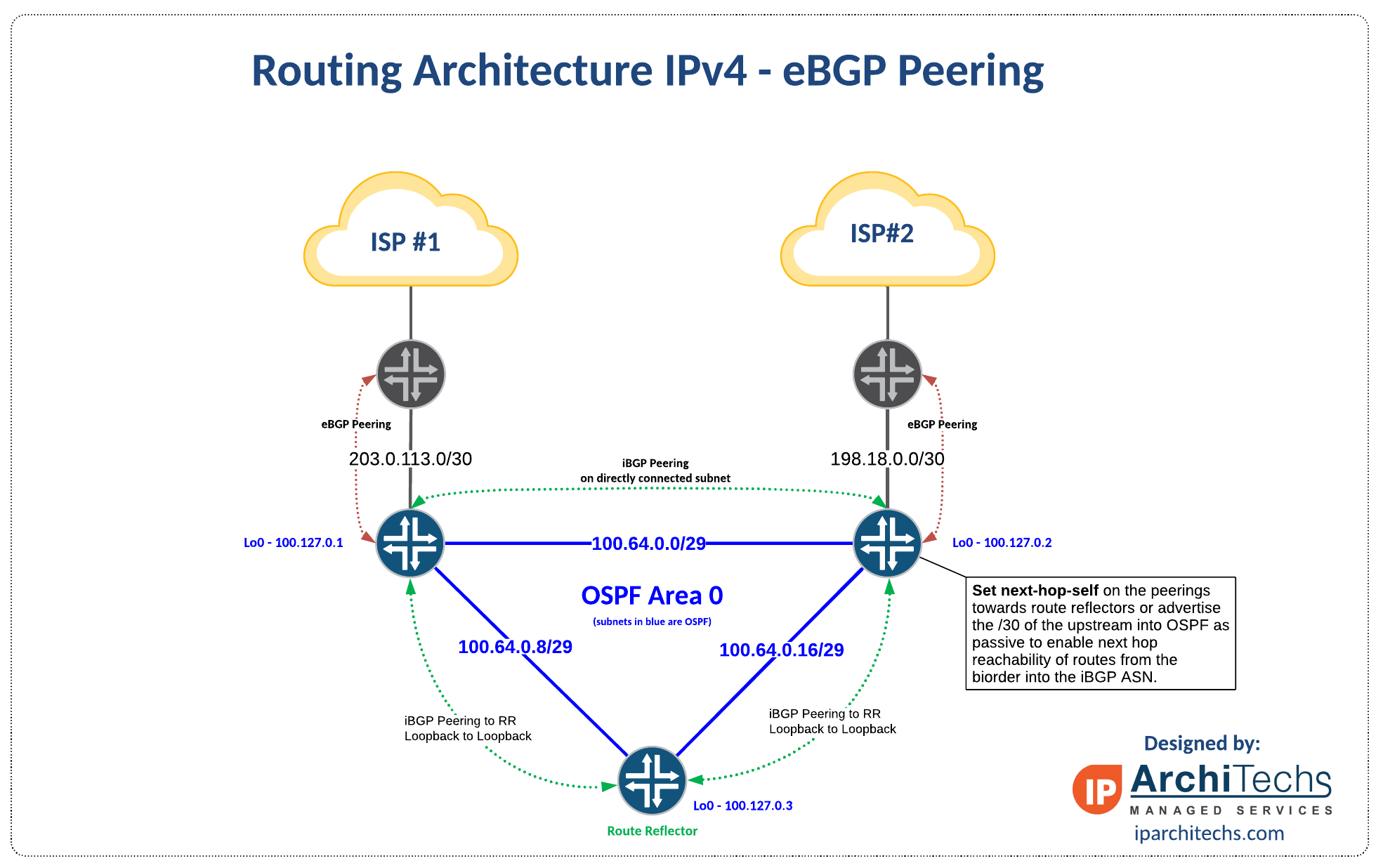
Depending on the path selection to remote networks on the internet BGP will choose to send traffic out to ISP 1 or ISP 2. The neighbor 2222 remote-as 64500 kind of command declares neighbor and says that it is located in AS 64500 BGP understands that the router itself operates in the same AS and further considers 2222 its IBGP partner. Instead of a physical device or appliance each Cloud Router consists of software tasks that.
The following diagram shows an example companys internet architecture using AS 1010 which is connected to ISPs using AS 101 and AS 201. BFD is a feature of BGP that applies to both public and private transit virtual interfaces. In this diagram Router 1 R1 and Router 2 R2 are in AS 100 which has external BGP eBGP peering with ISP-A AS 300 and ISP-B AS 400 respectively.
Lets take a look at the packet flow in reverse direction now. We will do this on the VLAN 1 interfaces of SW1 and SW2. The router in AS 1010 runs BGP and has formed neighborships between the two ISPs.
When you set up FastConnect virtual circuits you can choose to use private peering or public peeringThe details vary depending on whether you are using a FastConnect partner a third-party provider or colocation. In the diagram shown R101 learns prefix 10130130024 from R103 through iBGP and is. What should I specify as my address prefixes for the local network gateway when I use BGP.
R111 sets the community 1110 on the routes it advertises to R11. Cloud Router overview. User data is interspersed in-band with Telnet control information in an 8-bit byte oriented data connection over the Transmission Control Protocol TCP.
The first thing well do is enable HSRP. N-S Packet walk -Multi-Tiered Topology Return Packet. Telnet is an application protocol used on the Internet or local area network to provide a bidirectional interactive text-oriented communication facility using a virtual terminal connection.
R101show ip bgp. To extend your existing infrastructure into a virtual cloud network VCN in Oracle Cloud Infrastructure for example to implement a hybrid cloud or a lift.

Mpls Hub And Spoke Topology Ip Mpls Com
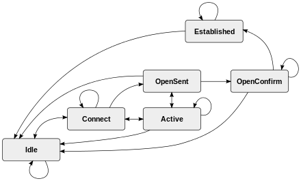
Border Gateway Protocol Wikiwand

Bgp Diagram Ccna Training Border Gateway Protocol Ccna

2 Service Provider Mpls Network On Single Cpe Active Active Ip Mpls Com

Border Gateway Protocol Wikiwand
Mpls Mesh Topology Ip Mpls Com
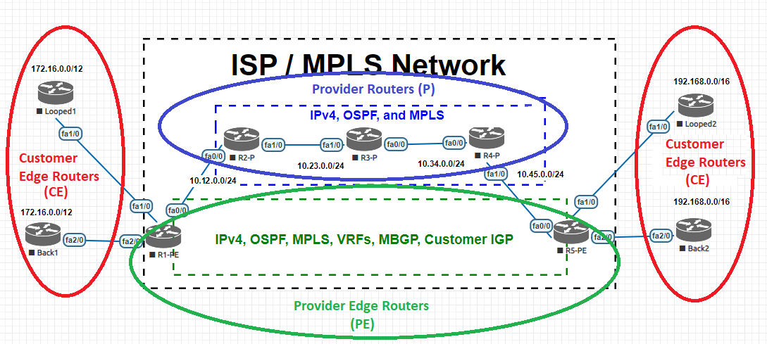
Mpls Layer 3 Overview Mbgp Configuration And Vrf Configuration Reviewed And How It All Works Together The Devnet Grind

2 Service Provider Mpls Network On 2 Cpe Active Active Ip Mpls Com
2 Isp 2 Router With Bgp And Osfp Mikrotik
2
2
2 5 Years Later The Network Diagram R Homelab
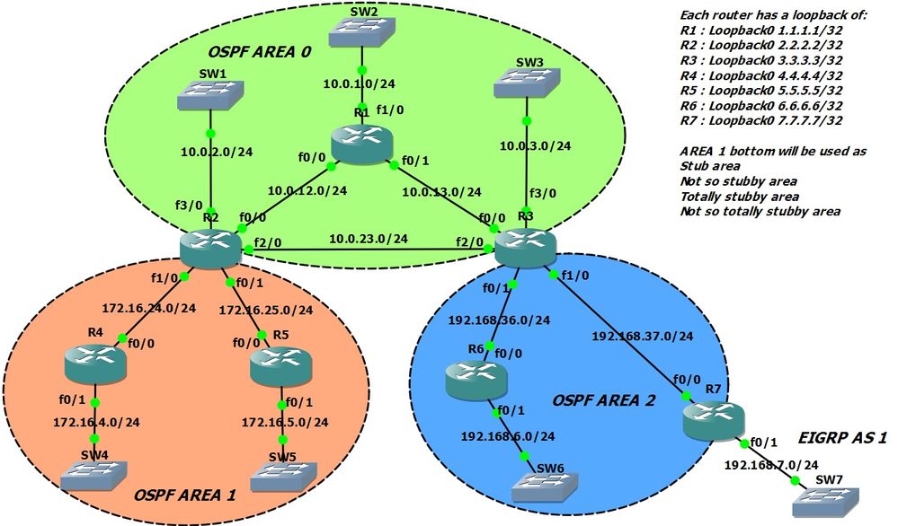
Solved Ospf Multi Area Route Inefficiency Cisco Community

Ospf Topology Database Design Optimization Principle Of Isp Igp Routing Apnic Blog
Networking Archives Jack Stromberg

Mpls Network Mesh Topology Dc Dr Setup Ip Mpls Com

2 5 Years Later The Network Diagram R Homelab